grblHAL motion controller · in development
Keep the machine.
Replace the brain.
ncCore is a controller that plugs into the harness your CNC already has. One mainboard, a small adapter card per machine, closed-loop motors treated as first-class, and an E-stop that cuts power in hardware. Built for ncSender.

Why it exists
Conversions fail in the wiring, not the firmware.
Every grblHAL board on the market assumes you rewire your machine to its terminal blocks. ncCore assumes the opposite: your harness is fine. A per-machine adapter card presents the stock connectors, so the swap is unplug, plug, flash.
Machine adapters
Your cables plug straight in.
The mainboard carries one 64-pin ribbon header and an XT30 motor bus to a stacked adapter card. The adapter is passive copper: it fans those signals out to the connectors your machine's harness already uses, so you never cut a wire. It is a few dollars of PCB, which is why every machine can have its own.
Onefinity Elite
Same eight-wire motor cables, same sensor plugs.
- Mini-Fit Jr motor connectors with 36 V, ground and signals in one cable
- Homing sensors, probe and tool setter on their stock plugs
- GX12 spindle port for 0–10 V VFD control, plus RS-485 Modbus the Masso never had

Onefinity Redline
The full RTS-2 connector set, routed and DRC clean.
- Five motor ports, five homing ports, probe, tool setter, PWM
- RS-485 for the VFD, flood and mist outputs
- Stands as the side panel of the enclosure

AltMill
SLB-EXT families, so the Sienci harness drops on.
- 2×4 keyed ribbon per axis with differential step, dir, enable and alarm
- 3.81 mm pluggable blocks for 48 V motor power
- JST XH limits, probe, tool setter, RS-485, spindle, coolant

Generic and DIY
Every signal on one keyed header.
- For scratch builds and machines nobody has made an adapter for yet
- The mainboard's own aux I/O is already on screw terminals
- Adapter design files are open, so the community can add machines
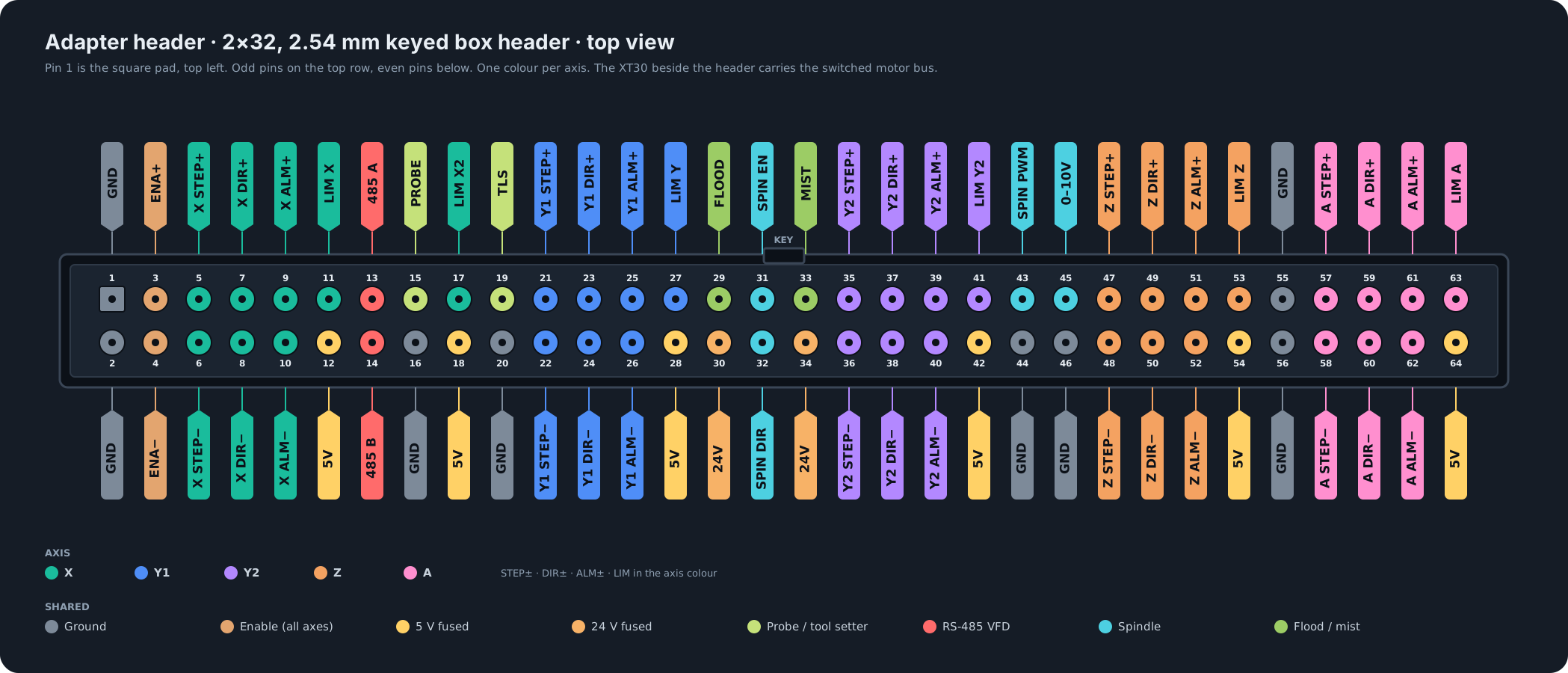 Open the full pinout with legend
Closed loop first
A stalled motor should stop the job, not ruin the part.
Closed-loop steppers report faults on an alarm wire. Most controllers leave it dangling. ncCore wires every alarm into grblHAL as a motor fault and drives step and direction differentially, so long cable runs and noisy VFDs do not turn into lost steps.
RS-422 step and direction
AM26C31 line drivers on all five axes. Differential pairs with no ground reference across the isolation barrier, the same signalling the closed-loop drivers on Onefinity, AltMill and MASSO machines already expect.
Five alarm inputs
Opto-isolated and polarity agnostic, so open-collector, driven or opto-pair alarm outputs all work. A fault raises a grblHAL alarm and the job halts with the position intact.
No drivers on board, on purpose
Drivers belong on the motor, where closed-loop integrated units already put them. ncCore stays small, cool and cheap, and a driver upgrade never means a controller upgrade.
Machine I/O
Everything a real machine hangs off a controller.
Field-side inputs and outputs are protected and galvanically isolated from the logic. Sensor supply voltages are selectable per bank, so NPN, PNP, 5 V, 12 V and 24 V devices all land without a resistor pack.

Power and safety
E-stop that firmware cannot argue with.
The mushroom sits in a hardware loop that drops the motor bus and the spindle permissive before any software knows about it. The controller stays alive on USB, sees the stop, and reports it, so ncSender keeps its connection while the machine is safe.
Board only, or boxed
Bare board for your own panel, or the optional enclosure.
Plenty of builders already run a panel box: contactors, relays, solenoids and the VFD on one back plate, wired the way they want it. For that build ncCore comes as the bare board. Four M3 corners, 145 by 93 mm, every connector on an edge, and the 64-pin header plus XT30 motor bus to bring into your own panel wiring, through the terminal adapter or an adapter of your own.
If you would rather not build a panel, the minimal enclosure is an optional add-on. Two parts, the adapter card standing as the end wall so the machine plugs face straight out, and the other end cut for the E-stop terminal, USB ports and antenna. Sold separately, so you only pay for it if you need it.

The ncSender stack
One vendor from the sender to the wire.
An ESP32-S3 radio lives on the board with its own USB-C and an external antenna. It carries Wi-Fi for ncSender, ESP-NOW for ncBridge wireless I/O, and four direct lines into the motion MCU so a wireless probe or tool setter trips with no latency. The ncSender pendant keeps working exactly as it does today, through its dongle.

ncSender · ncSender Pro
Built for this board
Firmware flashing from the app, job recovery, probing, tool changes and plugins. The sender knows the board's I/O by name.

ncBridge
Wireless I/O where the wire cannot go
Aux inputs and outputs on the moving parts of the machine. A dust boot sensor or a drawbar switch becomes a grblHAL input over the air.
Spec sheet
The numbers.
Current design as drawn. Specifications will be confirmed on production hardware.
| Motion | |
| Axes | 5 · X, Y1, Y2, Z, A · dual Y for gantry machines |
|---|---|
| Step / direction | RS-422 differential, 5 V, per axis · AM26C31 line drivers |
| Enable | Field-referenced, one shared enable, polarity set in firmware |
| Driver alarm | 5 opto-isolated inputs, polarity agnostic, mapped to grblHAL motor faults |
| Drivers | None on board. External closed-loop drivers, integrated or separate |
| Inputs and outputs | |
| Limits / home | 6, opto-isolated, 5–24 V, NPN or PNP, selectable sensor supply |
| Probe / tool setter | 2 dedicated inputs on 5 V, plus wireless probe and tool setter lines |
| Controls | Door, feed hold, cycle start, reset · dry contacts |
| Aux inputs | 8 in two banks, each bank 5, 12 or 24 V |
| Aux outputs | 4 protected low-side, 5, 12 or 24 V per output, plus flood and mist |
| Spindle | Isolated 0–10 V, PWM, enable, direction, isolated RS-485 Modbus RTU |
| Power and safety | |
| Input | 24–48 V DC, 100 V-rated front end, ideal-diode reverse protection, fuse, TVS |
| Motor bus | E-stop switched on board, soft start, 18 A limit, over-voltage lockout, XT30 out |
| Rails | 24 V, 12 V, 5 V field · isolated 5 V and 3.3 V logic |
| E-stop | Hardware loop, no firmware in the path, spindle permissive, bypass jumper for machines that cut the PSU |
| Isolation | Logic and field domains galvanically isolated, USB keep-alive when the PSU is cut |
| Compute and connectivity | |
| MCU | STM32F407, 168 MHz Cortex-M4F, grblHAL |
| Radio | ESP32-S3 · Wi-Fi and ESP-NOW for ncBridge · external antenna |
| USB | 2 × USB-C · MACHINE for ncSender and flashing · RADIO for the ESP32 |
| Machine interface | 64-pin ribbon header + XT30 motor bus to a stacked adapter card |
| Physical | |
| Board | 145 × 93 mm, 4 layers, M3 mounting on four corners |
| Firmware | Upstream grblHAL with an open board map |
Status
Prototypes are going to fabrication.
Leave an email and you will hear when boards and adapters are ready to order. Pricing is announced at launch. One confirmation email, then only release news.